Mailbox verification
Your email:
Verification Code:

    The SLP74AHC123A is a dual retriggerable monostable multivibrator with reset. This edge-triggered multivibrator features output pulse-duration control by three methods. In the first method, the A input is low, and the B input goes high. In the second method, the B input is high, and the A input goes low. In the third method, the A input is low, the B input is high, and the reset (R(D) input goes high. The basic pulse time is programmed by selection of an external resistor (REXT) and capacitor (CEXT).

    Once triggered, the basic output pulse width may be extended by retriggering the gated low-level-active (nA(() or high-level-active (nB). By repeating this process, the output pulse period (nQ = HIGH, nQ= LOW) can be made as long as desired. Pulse duration can be reduced by taking nRD low, which also inhibits the triggering.

    An internal connection from nR(D to the input gate makes it possible to trigger the circuit by a positive-going signal at input nR(D illustrate pulse control by retriggering and early reset. The basic output pulse width is essentially determined by the value of the external timing components REXT and CEXT. When CEXT 10nF, the typical output pulse width is defined as: tW = REXTCEXT, where tW = pulse width in ns; REXT = External resistor in k; CEXT = External capacitor in pF.


Main feature


  • Schmitt-trigger on all inputs

  • Inputs accept voltages higher than VCC

  • Edge triggered from active-high or active-low gated logic inputs

  • Retriggerable for very long pulses

  • Direct reset terminates output pulse

  • ESD protection:

  •  HBM  Exceeds 2000V

  •  CDM  Exceeds1000V

  • Latch-up performance exceeds 100 mA

  • Specified from -40°C to +85°C and from -40°C to +125°C


Ordering Information
Product Name Package form Marking Hazardous Substance Control Packing Type Remarks
SLP74AHC123AEC SOP-16-225-1.27 AHC123A Halogen free Tube
SLP74AHC123AECTR SOP-16-225-1.27 AHC123A Halogen free Tape&Reel
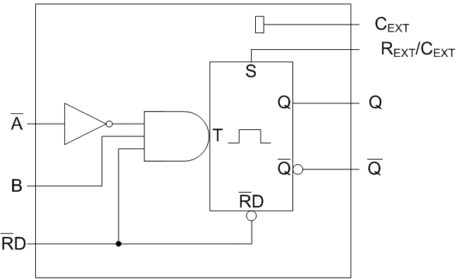
Block Diagram

123A.png

                                     Fig.1 Block diagram