Mailbox verification
Your email:
Verification Code:
SLP74AVCH2T45
2-BIT DUAL-SUPPLY TRANSCEIVER WITH VOLTAGE LEVEL TRANSLATOR AND 3-STATE OUTPUTS

    The SLP74AVCH2T45 is a 2-bit non-inverting bus transceiver uses two separate configurable power-supply rails. It features two data input-output ports (nA and nB), a direction control input(DIR) and dual supply pins (VCC(A) and VCC(B) ). Both VCC(A) and VCC(B) can be supplied at any voltage between 0.8 V and 3.6 V making the device suitable for translating between any of the low voltage nodes (0.8 V, 1.2 V, 1.5 V, 1.8 V, 2.5 V and 3.3 V). Pins nA and DIR are referenced to VCC(A) and pins nB are referenced to VCC(B).

    The device is fully specified for partial power-down applications using I OFF .The I OFF circuitry disables the output, preventing any damaging backflow current through the device when it is powered down.

When either VCC(A) or VCC(B) are at GND level, both A and B are in the high-impedance OFF-state.

    The device has active bus hold circuitry which is provided to hold unused or floating data inputs at a valid logic level. It does not recommend using pull-up or pull-down resistors with the bus-hold circuitry.


Main feature
  • Wide supply voltage range:

  • VCC(A):0.8V to 3.6V

  • VCC(B):0.8V to 3.6V

  • Bus hold on data inputs

  • I/Os are 3.6V Tolerant

  • I OFF circuitry provides partial Power-down mode operation

  • Maximum data rates:

  • 300 Mbps (1.8V to 3.3V translation)

  • 220 Mbps (<1.8V to 3.3V translation)

  • 200 Mbps (translate to 2.5V or 1.8V)

  • 150 Mbps (translate to 1.5V)

  • 100 Mbps (translate to 1.2V)

  • ESD protection:

  • HBM Exceeds 8000V

  • CDM Exceeds 1000V

  • Latch-up performance exceeds 100mA

  • Specified from -40°C to +85°C and -40°C to +125°C


Ordering Information
Product Name Package form Marking Hazardous Substance Control Packing Type Remarks
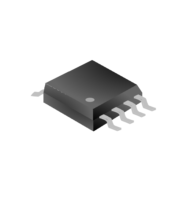
SLP74AVCH2T45JWTR VSSOP-8-100-0.5 2T45 Halogen free Tape&Reel
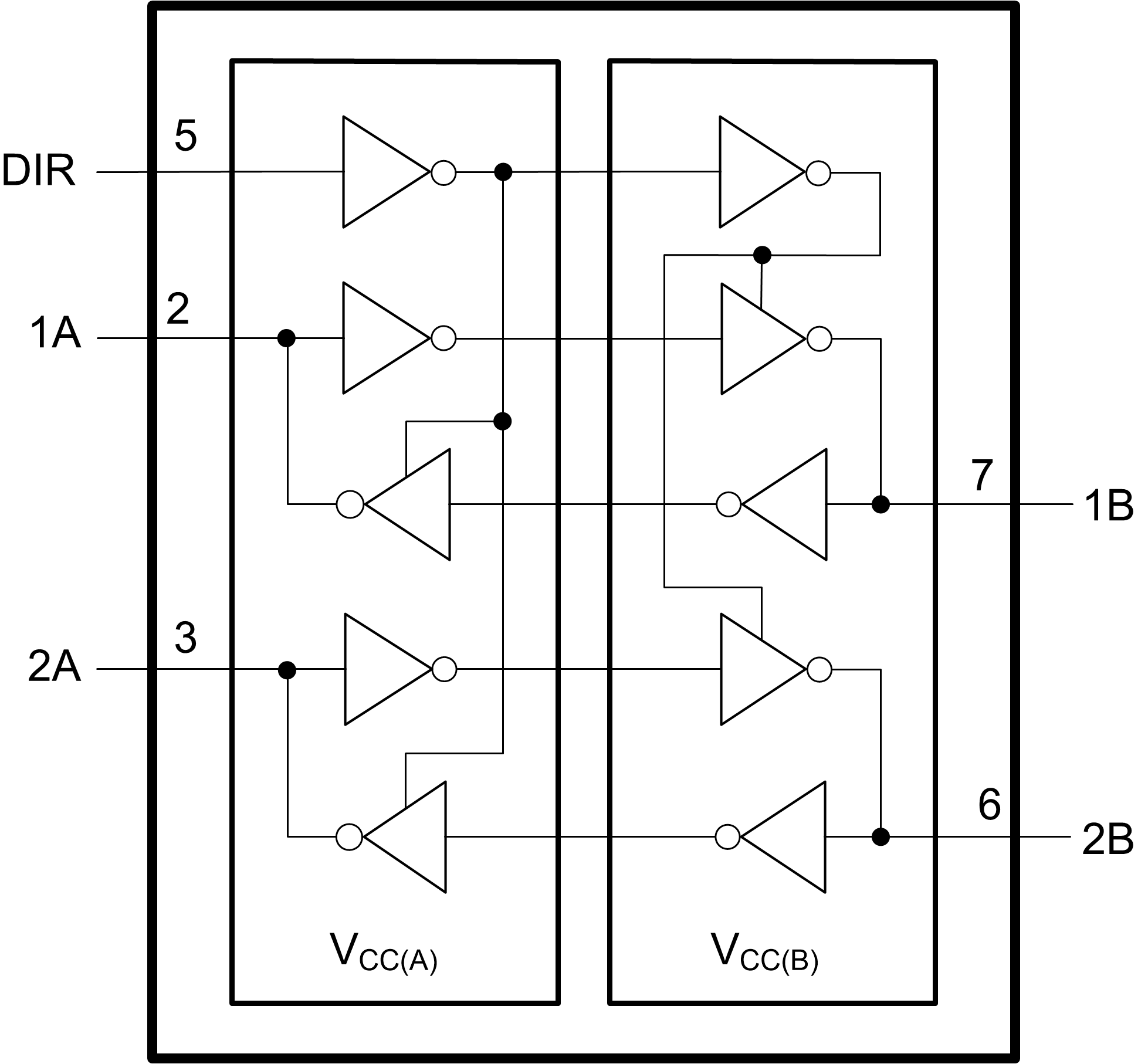
Block Diagram


SLP74AVCH2T45.png

                                                     Fig.1  Logic symbol